|
|
|
|
Conductivity with the BS2/OWL2
|
conductivity or moisture sensor using 555 timer |
|---|
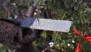
- -- the measurement of wetness on an artificial leaf surface.
- Moisture deposited on a surface bridges across a grid of wires or circuit board traces. A circuit measures the AC ohms resistance through the grid. -- Warm wet weather promotes fungus and insect pests of plants. -- Quick detection of rain can be used in controllers for greenhouse windows and the like. -- Grids can be used to detect the moisture in breath, condensation from steam, or spray from industrial or other processes.
- -- measurement of soil moisture via gypsum or watermark sensors
- Stainless steel electrodes are embedded in a block of plaster of paris (gypsum) or in a proprietary mixture. Watermark™ sensors are "granular matrix" devices, that have a fine sand aggregate along with gypsum crystals, held inside a permeable membrane and stainless steel sleeve. The purpose of the gypsum is to buffer the conductance measurement from ions that are found in uncontrolled amounts in the soil. This device is buried in close contact with soil, and reaches an equilibrium with the soil moisture. The AC ohms resistance of the block can be correlated with soil moisture or with evidence of plant stress. We have an assembled "SMX" module available for reading the resistance of Watermark blocks into the OWL2 or BASIC Stamp.
- --liquid level control
- Electrodes touch the surface of the water, to indicate attainment of a certain water level. This can initiate an action or alarm, or operate a sump pump. An output can be taken as the water moves up and down a pair of electrodes, and the level is correlated with resistance values on the scale. The signal depends on both the water level and on the specific conductivity of the water. See Earth Measurements, units 5 and 6.
- --actual measurement of conductivity of water, or ionic concentration.
- By making the water fill an exact geomerical space, the variable becomes the conductivity of the water. The circuit measures the resistance of the water at a certain temperature, which is measured at the same time. Multiplying by a geometry constant of the cell gives the conductivity at that temperature. Usually conductivity is reported as the value it would have at a reference temperature, such as 25 degrees C. From this then the concentration of ions can be inferred, if the types and percentages of ions present are known in advance.
|
|
|
|
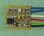
The power supply voltage is regulated at 3 volts DC by the micropower Toko TK1530SCLCT. The + power input can be as low as 3.5 volts and as high as 15 volts. Filter capacitors are provided for stability. The CMOS LMC555 timer operates in its direct feedback mode, with a square wave on the totem pole output from pin 3 charging or discharging the 0.1 µf film capacitor through the network of fixed resistors in series/parallel with the conductive sensing grid. When the grid is dry, the 150k˝ 1% resistor sets a minimum oscillator frequency of 50 hertz. When the grid is wet, or short circuited, the 390˝ 1% resistor in series with the two 1 uf capacitors and the grid limit the upper frequency to about 10 khz. The impedance of the two capacitors is in series with the grid, and the reactance is near 3000 ohms at 50 hertz (compare to 150 kohm), and 15 ohms at 10000 hertz (compare to 390 ohm). This circuit is available from EME Systems (SMX).
The current through the sensing grid is AC. The 555 timer itself provides this AC excitation, as it alternately charges and discharges the film capacitor through the grid in parallel with the 150kohm resistor. The 2.2 uf non-polar capacitors in series with the grid assure that even the nanoamp level leakage currents from the CMOS chip do not flow through the grid. The capacitors, one being on each side of the grid, also assure that this circuit is galvanically isolated from other sensors that might be immersed in the same aqueous environment.
The output frequency is transmitted from the open collector DIS output pin on the '555. Normally a pullup resistor is provided to give 5 volt square wave that feeds to the data logger or readout circuit. Alternatively, the current drawn by the 555 timer circuit varies linearly in proportion to the frequency of oscillation due to the charge and discharge cycles of the timing capacitor. Thus, the supply current can be used as an analog signal, to send to an analog to digital converter. The resistor Rset=~56.3 kohms is used to preset a supply current of 200 microamps when the sensor is dry. The current develops a voltage across the 1kohm resistor, to give a voltage signal if desired.
Connect the X555 as in the figure, for digital (frequency) output. The following programs are in PBASIC for the BASIC Stamp. The programs use the PBASIC command COUNT to determine the oscillation frequency of the X555.
' simple test of the X555 operation.
x	var  word
loop:
  count 12,1000,x   ' count X555 on Stamp P12
  debug ? x         ' show the result
goto loop
Here is a routine for the OWL2c. The refinement is that it counts for only 0.1 second, and it clamps the input so that it can not exceed the 100% value, set at a count of 1000 per 0.1 second.
' refined program, for OWL2c.  Presents result as percent
' counts for 0.1 second and clamps result at 100%
result	var word
x555_pin	con 12
x555:
  count,x555_pin,100,result    ' count for 0.1 sec
  result = result max 999/10   ' for 0 to 99%
  debug dec2 result, "%"
goto x555
Here is a routine that scans 4 x555 sensors connected to Stamp pins 12 to 15, OWL2c i/o 5 to 8..
' scans 4 x555 sensors, and presents result as % x555
' counts for 0.1 second and clamps result at 100%
result	var word
ix	var nib
x555_pin	con 12
x555:
  debug home
  for ix=0 to 3
  count,x555_pin+ix,100,result
  result = result max 999/10   ' for 0 to 99%
  debug dec2 result, "  %LWET",dec ix,cr
  next
goto x555